
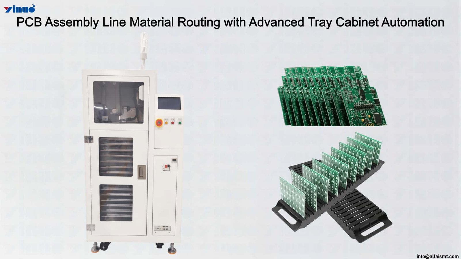
Introduction
The Tray Cabinet combines tray capacity, programmed movement and component presentation in a single automated material handling platform. Its storage section supports 15 trays with a maximum tray size of L240 × W350 × H30 mm, making the cabinet suitable for production setups where multiple component trays need to remain available during automated operation. The 220V electrical supply and 4–7 BAR pneumatic system provide the operating conditions for its tray lifting, movement and material handling functions. The cabinet architecture separates manual tray access from automatic component transfer, creating distinct operating zones within the equipment.
A significant performance characteristic is its cyclic material delivery control. The feeding mechanism can maintain continuous material feeding for 2 seconds during each programmed cycle, with ten feeding cycles specified in the operating sequence. Tray rotation then incorporates a 3-second waiting period before the next movement stage. This programmed timing gives the cabinet controlled movement intervals and prevents tray positioning from becoming an uncontrolled part of the material supply process. The tray base lifting function also establishes the working level required for component extraction, allowing the transfer mechanism to approach the selected tray location under defined mechanical conditions.
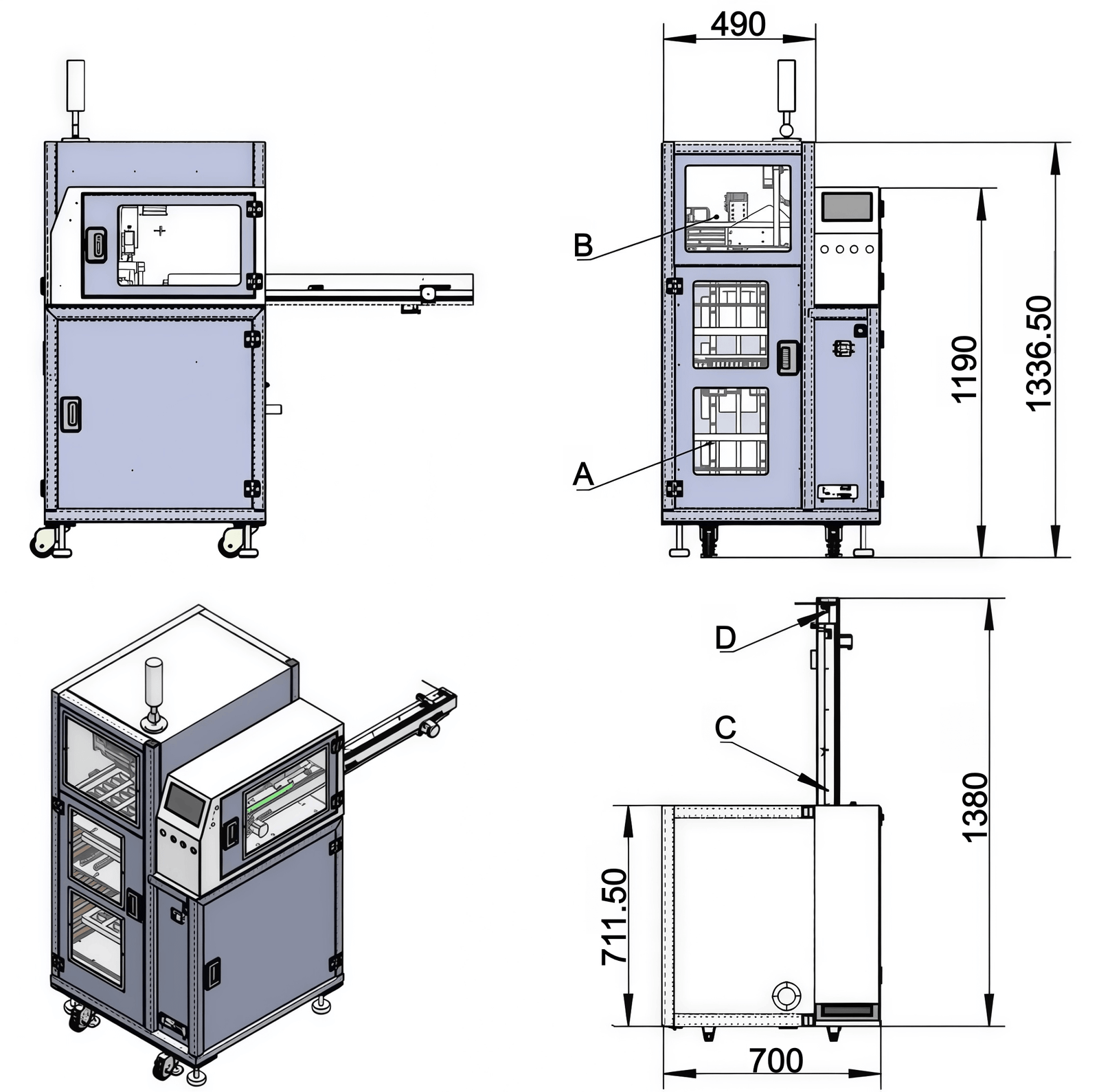
The XY transfer system provides coordinate-based retrieval. Components are collected from designated tray positions through suction cups or clips and transferred to the C feeding track. The material exit can be configured according to the connected insertion equipment, with separate arrangements for tape-based delivery or direct placement. Positioning data can be modified for different equipment models. At the D pickup location, the cabinet presents the component to the insertion machine and can incorporate material flipping when orientation correction is required. This combination of cyclic control, multi-tray storage, coordinate retrieval and orientation handling defines the Tray Cabinet as an active material processing unit rather than a simple storage cabinet.
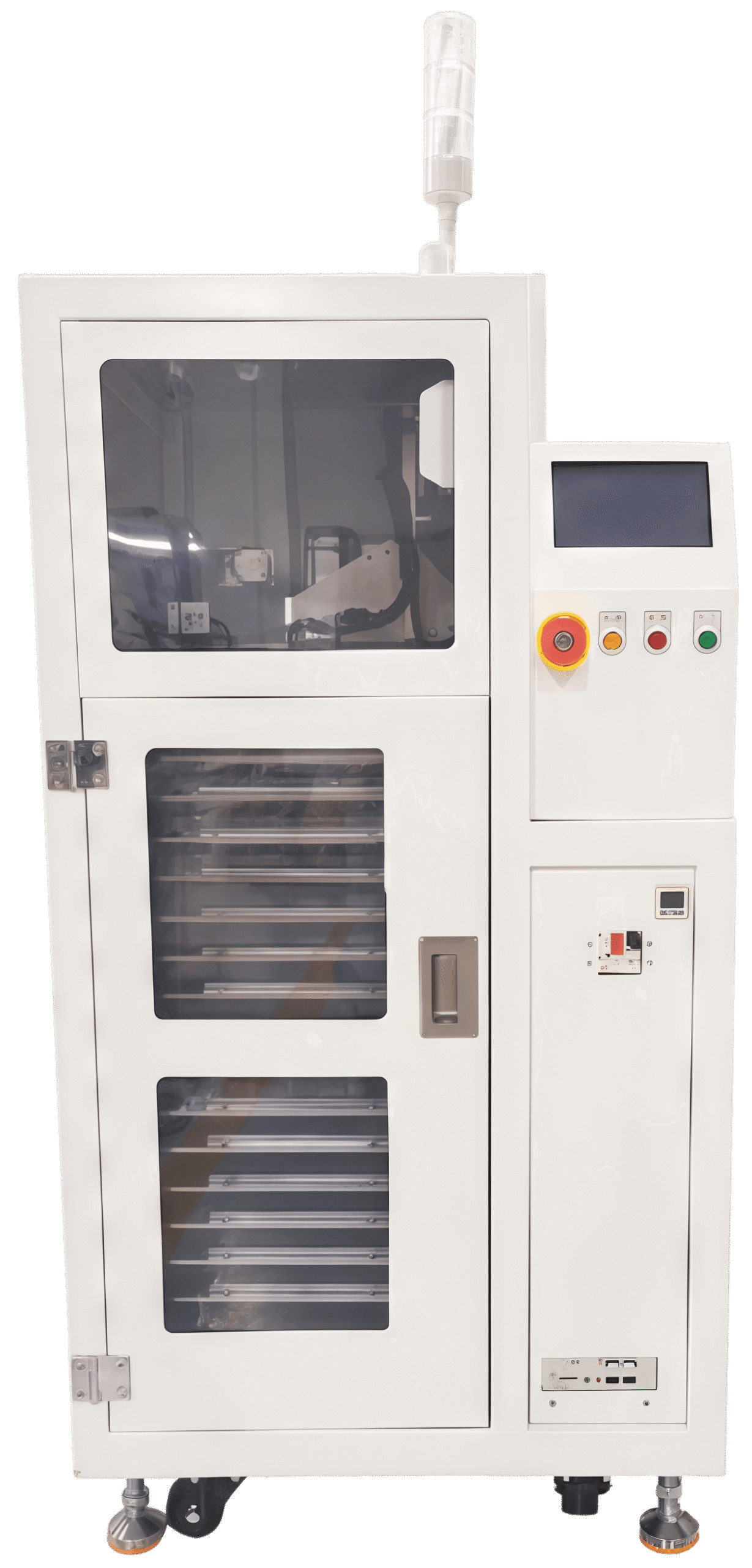
Tray Cabinet
Tray Cabinet for PCB Production Lines Requiring Flexible Component Feeding and Automated Insertion Equipment Handoff
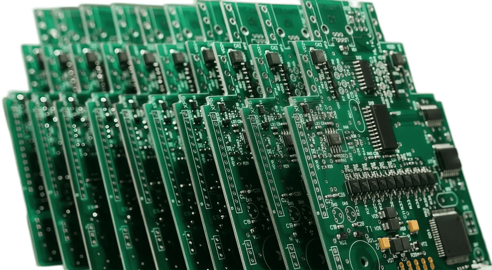
For PCB assembly factories producing several board models within the same production schedule, the Tray Cabinet can function as a centralized source for tray-based insertion materials. Different work orders may require different component types, quantities and feeding arrangements. The cabinet provides space for up to 15 trays, enabling prepared component groups to remain available near the insertion line. Operators can load empty trays or replace material-filled trays from the external placement area, while the automatic transfer mechanism remains separated from manual handling.
During a production changeover, trays can be prepared according to the component list of the next PCB model. Once the appropriate tray is selected, the tray base is lifted to establish the required transfer reference. The XY axis then moves to the programmed component position and transfers the material with a suction cup or clip. This coordinate-based retrieval method allows the same cabinet concept to handle components from different tray locations without requiring operators to manually move individual parts to the insertion machine.
The downstream connection is established through the C feeding track and D pickup area. Materials can be routed according to whether the receiving insertion machine uses tape-based feeding or direct placement. Positioning information can be modified according to the connected equipment model, which allows the material presentation point to correspond with different insertion-machine configurations. When component orientation needs to change before pickup, the flipping function can be applied at the presentation stage. In this way, the Tray Cabinet becomes part of the PCB production changeover process, connecting prepared tray materials with the insertion equipment while keeping the material route organized.
Specifications
| Model | YN-C2501 | |
| Dimensions (L×W×H) | 1380×700×1361.5 | Unit: mm |
| Weight | 213.5KG | |
| Operating Voltage | AC 220V | |
| Air Supply Required | 0.5–0.7Mpa | |
| Maximum Power | 750W | |
| Feed Speed | 2s/Pcs | |
| Operation Panel | 7″ IPS 1024*600 Display Screen | |
| Channel | Single Channel | |
| Function | Optional | |
| Applicable Tray | Please refer to the drawing below | Default: None |
| Overall Configuration | Sensors and sensor control devices use loose brands; motors use Panasonic; solenoid valves use Airtac; touch screen uses Leisai; wire harnesses are custom-made; control system uses industrial controller. |
https://www.youtube.com/@allaismt
For more information about the Tray Cabinet, please send an email to
We will respond to your inquiry promptly and provide you with detailed information about our products and services.