Return to previous page

Automatic Radial Component Insertion Machine

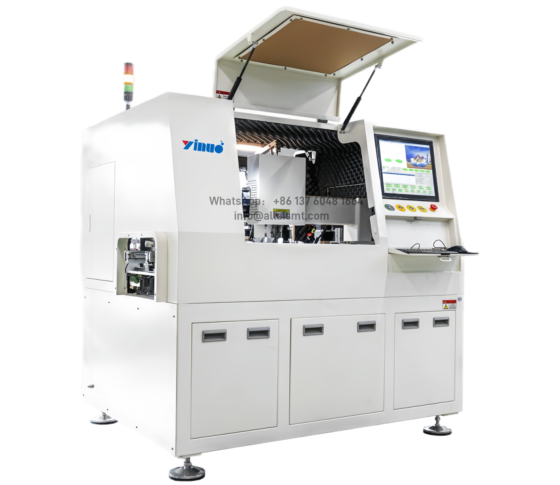
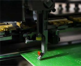
An Automatic Radial Component Insertion Machine is a specialized piece of equipment used in electronics manufacturing for automatically inserting radial leaded components—such as resistors, capacitors, and diodes—into printed circuit boards (PCBs) before soldering. These components have two leads coming out of the same side, typically used in through-hole mounting.


PCB Axial Insertion Machine

AC Terminals Insertion Machine

TAB Terminal Insertion Machine

Jumper Wire Axial Insertion Machine

PCB tactile switch insertion machine

Auto PIN Lead Cutter Machine

Automated radial insertion equipment for printed circuit board assemblies increases production capacity to meet the growing demand for printed circuit board assemblies. Radial insertion machines are essential for applications such as power circuits and motor drives, and eliminate the need for a separatemanual lead trimming step. It improves quality by compacting component leads as they are inserted, resulting in consistently strong solder joints and easier board handling. By combining automated and manual insertion of through-hole components,highest yields and lowest labor costs in precision electronics manufacturing.

Radial insertion machine tapping specification

Markers / Content / Parameter
W1 / Tape hole center to component center/ 6.35mm ro 7.5mm
W2 / Pitch of holes /12.7/15mm
H1 / Pin wire protruding length / 0
H2 / Tape center to component base /18mm
H4 / Components taping width /18mm
H /Tape center to component top / h2+h3≤41mm
D1 / Pin wire diameter / Ø=0.6-10±0.1mm
D2 / Hole diameter / 4±0.2mm
M / Tape thickness / ≤ 1.2

Radial insertion Claw width interference

Radial inserter claws
Single insert.span 2.5mm
Two types insert.span 2.5/5.0mm
Three types insert.span 2.5/ 3.5/7.5mm
Three types insert.span 2.5/ 5.0/7.5mm
Four types insert·span 2.5/ 5.0/7.5/10.0mm

Trimming length and bending angle

Insert the radial components into the preset holes on the PC8 with a fxedspan and cut and bend the bottom component pins. The rivet shape on the printed board is shown in the fgure

Claw back interference

The angle of the claw is 45 “, and after the inseris completed, it should be noted that the heightand distance of the inserted components behinthe claw and the patch components interfere wit!each other

Claw+lead clipper interference

there mabe spatial interference during inserton and footcutting operatons. No other components shouldbe installed in the safety area to avoid toolcollisions and PC8 board damage

Radial insertion machine

A high-density radial lead component insertion machine, the R-8800 with guide pin system provides stable, high-density insertion at 14,400 cph (0.25s/component). This through-hole machine inserts components with a pitch range of 2.5mm, 5.0mm or 7.5mm and allows for 10 or 40 component inputs – a wide component range in a compact footprint with a low cost of ownership. Full auto-recovery corrects insertion errors while the part exhaust detection system allows for proactive part replenishment and promotes continuous productivity. 4 insertion directions (0°, 90°, -90°, 180°) Wide pitch range encompassing 2.5/5.0/7.5 and 10 mm pitch in a common platform – eliminating the need for post insertion manual placements of 10 mm pitch components Auto-recovery and part exhaust detection

Radial insertion machine (10 feeder)

1)four Span:2.5/5.0/7.5/10.0mm
2) 18000 CPH,actual speed 14400 CPH
3) Insert direction:0° -360°, 1°increasment
4) Servo motor drived insertion head(13.0mm)and clinch base “N” type. – 5) Components available:Capacitor, Transistor, LED lights, Key Switch, standard tape packed radial leads components
6)Core Machine Size (LxWxH)1800x1600x1800mm,
7) Machine Weight:1000KG –
8) Power supply:220V, AC (single phase) 50/60 HZ –
9) Air pressure:0.6MPA;0.3M3/MIN –
10) Circumstance temperature: 10° C. to 35° C. –
11) PCB Size:(Min)50 mm x50mm、(Max)400mm x 280mm –
12) PCB thickness:0.79-2.36MM –
13) Clinch Length:1.5-2.2MM –
14) Clinch degree: 10-35 degree –
15) Coordinate correction:Machine vision systems –
16)Non rotary table –
17) Machine vision caliberation systems
18) Control System:English or Chinese version interface
19) Feeder: 10 units 15 units 20 units

Insertion head

PCB fixing platform

Chain tension adjustment

Radial  Insertion head and cutting head

Radial Insertion Machine Feeder

Tape cutting device

PCB conveyor track

Material clamp carrier chain

Electric control box

Claw interference+component lead clipper interference

The radial insert machine claws is close to the front of the Pcb board and requires a certain safe working space. As shown in the figure, it should be at least 1mm away from the center of the insert pin hol.When perorming the foot trimming action, the foot trimmer will rise close to the bottom of the board (opposite side) and also require a safe working space. D.lf the diameter of the component body is greater than the span of the insert the clawsinterference will increase the corresponding range, and the shear foot interference wilremain unchanged

SMT Magazine loader

This unit is used for loading of PCBs from the production line.

SMT Magazine unloader

This unit is used for unloading of PCBs from the production line.