
مقدمة
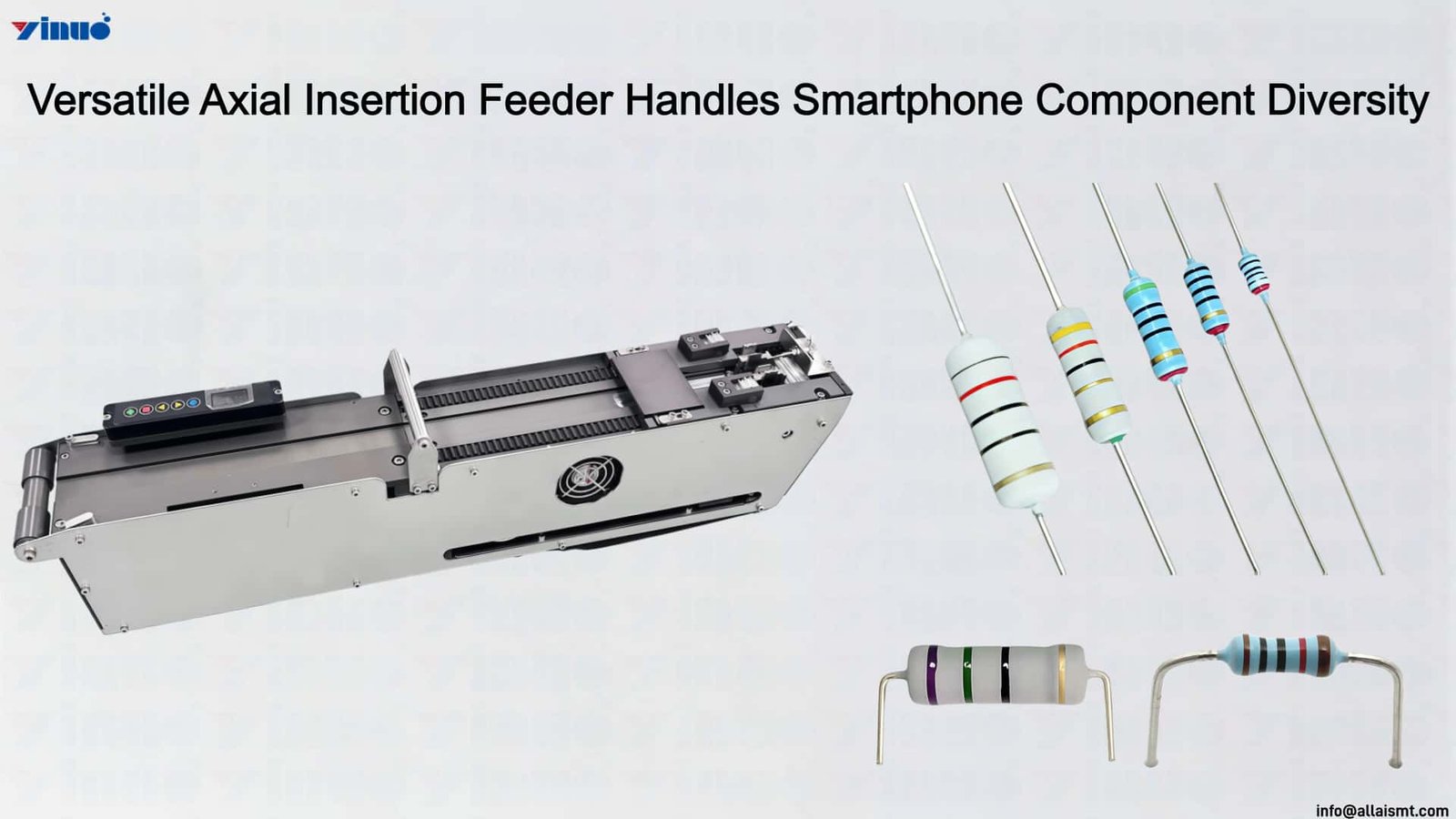
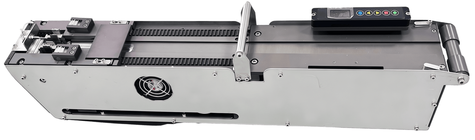
ال Axial Insertion Feeder processes axially taped components in strip format—resistors, diodes, and jumper wires—advancing each component through tape peel-off, lead straightening, and pickup presentation in a continuous mechanical sequence. The tape guide channel is machined to the exact strip width and inter-component pitch of the customer production reels, preventing tape skew and component rotation during advancement that universal feeders frequently introduce when handling non-standard strip dimensions.
The tape drive mechanism grips both edges of the carrier strip simultaneously, applying balanced traction that maintains component axial alignment from peel-off through the staging gate. A spring-loaded tensioning roller compensates for tape elasticity variation between reel batches, preventing the slack accumulation that causes skipped feed cycles when tape stretch differs from the nominal specification. The feeder bandwidth capacity—the range of strip widths, lead diameters, and component body sizes it processes—exceeds OEM-standard limits through the custom track geometry rather than through interchangeable tooling inserts.
After tape separation, the leads pass through a straightening roller set that corrects minor axial curvature before the component enters the cutting zone. This pre-straightening step ensures that the U-clamp forming operation acts on leads with consistent entry geometry, producing uniform clinch angles regardless of how the tape was wound on the supply reel. The straightened leads seat predictably in the insertion head gripper, reducing pickup misalignment during sustained operation and supporting the high cycle counts that axial component insertion lines demand across extended production shifts.
وحدة التغذية المحورية
Modular Scalability of the Axial Insertion Feeder Across Smartphone Electronics Factory Generations
ال axial insertion feeder operates at the intersection of mechanical precision and thermal-material science, confronting challenges uniquely amplified within smartphone manufacturing’s aggressive miniaturization trajectory. As smartphone PCBs incorporate increasingly diverse axial component packages—ranging from glass-bodied diodes to polyester-film capacitors—the feeder must accommodate a spectrum of material sensitivities without compromising delivery cadence. Thermal equilibrium within the feeder cassette becomes a critical variable, as differential expansion between carrier tape and component leads can induce subtle pitch drift cascading into insertion misregistration downstream.
The feeder’s thermal management strategy employs passive and active elements in concert. Passively, the cassette body is engineered from thermally stable polymer composites whose coefficient of thermal expansion is closely matched to the component carrier tape, minimizing dimensional variance across the temperature fluctuations inherent to a factory floor. Actively, localized micro-pneumatic channels regulate airflow across the component presentation window, evacuating residual heat generated by the insertion head’s solenoid actuators before it can radiate back into the feeder cassette and destabilize lead geometry of queued components.
Smartphone manufacturers can incrementally scale insertion capacity by adding feeder modules rather than commissioning entirely new insertion lanes, converting what would be a discrete capital expenditure decision into a granular, demand-responsive investment trajectory. When a product nears end-of-life, the same feeder modules redeploy to new lanes supporting successor products, preserving capital utility across product generations and insulating the factory’s balance sheet from the steep depreciation curves that characterize purpose-built insertion machinery.
تحديد
| نموذج | YN-A2101 | YN-A2208 |
| Dimensions (Length * Width * Height Unit: mm) |
570×90×140mm | 570*127*150mm |
| وزن | 8.5KG | 14KG |
| Operating Voltage | DC 24V | |
| الكمية المطلوبة من الهواء | None | |
| التيار الأقصى | 3A | |
| سرعة التغذية | 1.5–2 s/Pcs | 2.5–3 s/Pcs |
| Drive Mode | كهربائية بالكامل | |
| لوحة التشغيل | 0.96″ TFT Color ScreenResolution: 80×160 pixels | |
| Material Lifting Error | ±0.4mm | |
| Applicable Tape Width | 60–66mm | 63-90 mm |
https://www.youtube.com/@allaismt
For more information about the Axial Insertion Feeder, يرجى إرسال بريد إلكتروني إلى
سنرد على استفسارك على الفور وسنزودك بمعلومات مفصلة حول منتجاتنا وخدماتنا.