Introducción
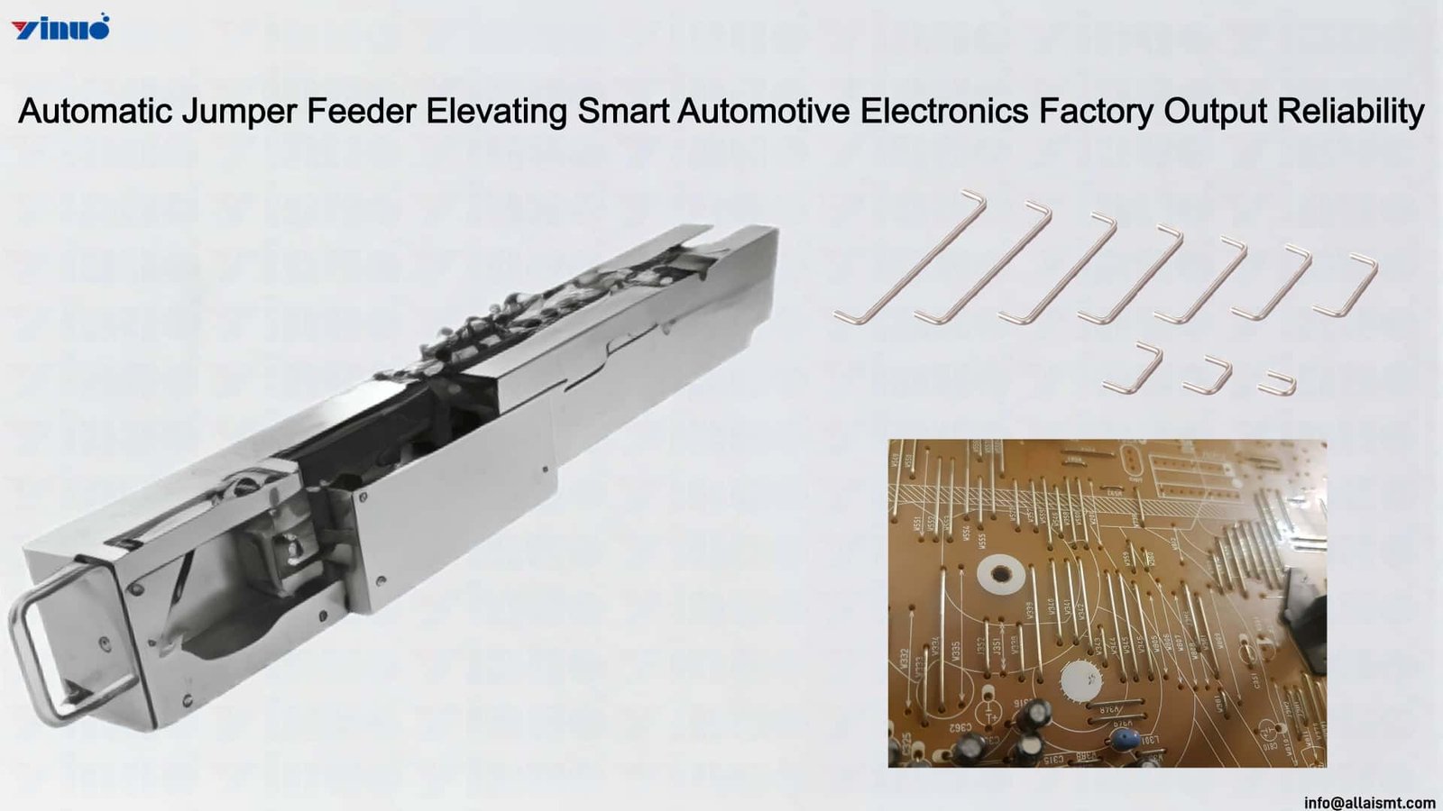
The final stage of the Alimentador automático de puentes‘s processing path, where each cut jumper segment is presented for pickup by the placement nozzle, constitutes a critical precision interface that determines whether upstream cutting and conditioning accuracy is transferred to the placement operation. Here, the feeder must hold each segment in a defined position with controlled lateral, longitudinal, and vertical stability, ensuring the descending nozzle fully engages the jumper at the intended acquisition point. The presentation mechanism employs a precision-machined nest or cradle feature that receives the cut segment from the advancement path and seats it against positive stop surfaces, establishing a repeatable reference position that the placement machine can target.
The vertical stability of the presented segment is particularly significant for reliable nozzle acquisition. A jumper that sits too high risks being contacted prematurely by the nozzle during its descent, potentially displacing the component from its seated position before vacuum engagement is established. A jumper seated too low may not enter the nozzle’s effective pickup range, resulting in a missed acquisition that triggers an error cycle. The Automatic Jumper Feeder controls vertical positioning through a spring-loaded or compliant seating surface that applies consistent downward bias to the cut segment, pressing it into a defined vertical reference regardless of minor variations in wire diameter or residual straightness. This compliant seating accommodates dimensional variation while maintaining a predictable vertical presentation height.
Lateral and longitudinal stability at the pickup position is maintained through sidewall constraints within the nest geometry that prevent the cut jumper from shifting under the impact of nozzle contact or under vibration transmitted from the placement machine during rapid head movement. The nest sidewalls are positioned to allow the nozzle to access the segment without interference while preventing lateral displacement during the acquisition instant. This precise presentation geometry, combined with the sensor verification that confirms segment presence and proper seating before the placement head descends, ensures that nozzle acquisition occurs reliably on every cycle, converting the feeder’s upstream processing precision into consistent, repeatable placement outcomes.
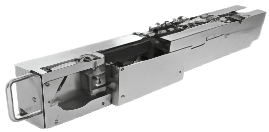
Alimentador automático de puentes
Deploying the Automatic Jumper Feeder Across Mixed-Model Automotive Electronics Lines
In smart automotive electronics factories, the Alimentador automático de puentes integrates directly into surface mount technology pick-and-place systems to supply jumper components—configurable link resistors and bridge connectors—without manual tape-loading interruptions. Its motorized tape-advance mechanism synchronizes with the placement head’s pickup cycle, presenting a component at the pickup position within every placement interval. This eliminates the indexing delay conventional feeders introduce, keeping the placement head in continuous motion across long production runs for automotive electronic control units and sensor modules.
Automotive electronics production frequently shifts between printed circuit board variants—engine controllers, infotainment boards, body control modules—each demanding different jumper values. The Automatic Jumper Feeder accommodates multiple industry-standard tape widths through a tool-less changeover design, enabling swift reel swaps. Auto-calibration of component pitch upon reel loading removes the manual sprocket-alignment step, reducing line idle time during product transitions and supporting the mixed-model scheduling that leading suppliers rely on for just-in-time delivery.
During extended campaigns, the Automatic Jumper Feeder maintains feeding precision through a tension-controlled tape transport that prevents component shift, tape wrinkling, and mis-pick events. Anti-static guide rails protect jumper components from electrostatic discharge damage—critical for automotive electronics qualification compliance. By sustaining a stable presentation rate across continuous pickup cycles, the feeder reduces defects from missing or misaligned jumpers, ensuring boards pass automated optical inspection on initial scan and minimizing rework on safety-critical automotive assemblies.
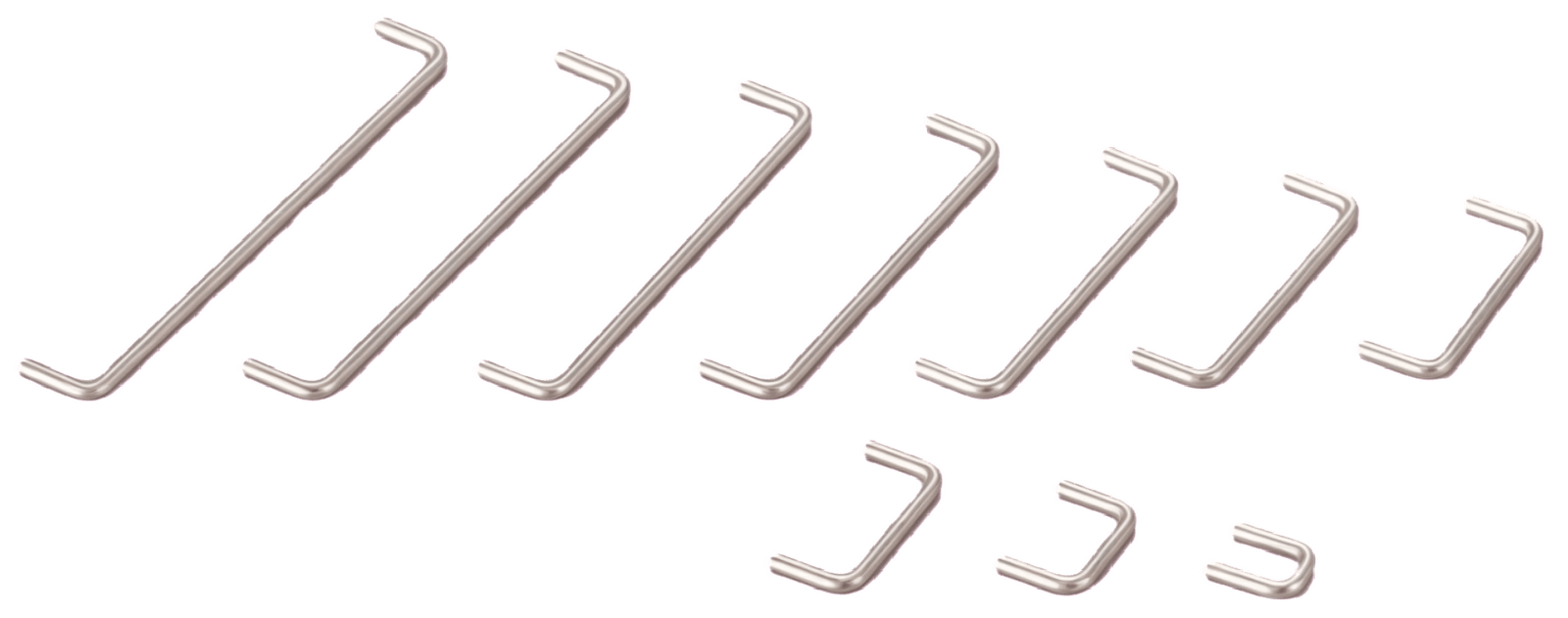
Presupuesto
| Modelo | YN-J2303 | Observaciones |
| Dimensiones (largo × ancho × alto) | 624 × 78 × 160 mm | |
| Peso | 6,5 kg | |
| Operating Voltage | DC 24V | |
| Suministro de aire necesario | None | |
| Corriente máxima | 2,5 A | |
| Feed Speed | 1,5 s/unidad | |
| Panel de operaciones | TFT de 0,96″ Resolución de la pantalla a color: 80 × 160 píxeles |
|
| Tiempo de cambio | 3 min | |
| Canal | Un solo canal | |
| Función de doblado de plomo | Flexión | |
| Función previa a la elevación | Servicio de recogida previa disponible | |
| Función de corte | Límite | |
| Función de corrección | Corrección | |
| Diámetro del alambre del material | 0,4–1 mm | No se puede utilizar una matriz de conformado de 0,6 mm para conformar un alambre de 0,4 mm; Solo se puede utilizar una matriz de 0,6 mm para un alambre de 0,6 mm. |
| Distancia entre carriles | 5–26 mm (La matriz de conformado depende del diámetro del alambre) Molde en forma de cruz: 3 tamaños en un solo juego (grande/mediano/pequeño) |
No se puede utilizar la matriz de conformado de 16 mm para un paso de vía de 16 mm; Se debe utilizar una matriz de 16 mm de longitud |
| Longitud del plomo de conformado | 2,0~5,5 mm | Dentro de este rango, solo es posible obtener diferentes longitudes utilizando diferentes matrices de conformado de los tamaños correspondientes |

https://www.youtube.com/@allaismt
For more information about the Alimentador automático de puentes, por favor envíe un correo electrónico a
Responderemos a su consulta a la brevedad y le proporcionaremos información detallada sobre nuestros productos y servicios.