

BGA Solder Ball Feeder for BGA PoP and Semiconductor Packaging
How It Works
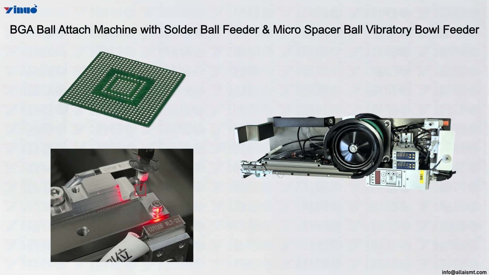
The BGA Solder Ball Feeder supplies individual spheres for placement on substrates, package terminals, or other designated attachment locations. A bowl feeder separates suitable balls through vibration and guides them toward a pickup point, while an indexed carrier presents miniature balls in predetermined positions. The placement head retrieves each sphere through a compatible vacuum nozzle and transfers it according to the programmed package layout. This process can be considered for inline use when the host machine has sufficient motion clearance and the required placement capability.
Ball Size Coverage
Available configurations cover different operating ranges. Bowl-based systems typically handle 200–800 µm spheres at 8–40 balls per minute. An indexed carrier can accommodate approximately 75–150 µm miniature balls at 4–8 balls per minute, with vision counting available for the relevant configuration. Selection should consider ball diameter, diameter variation, alloy, carrier design, nozzle aperture, and required output. The nominal feed rate should not be treated as a guaranteed placement rate without application testing.
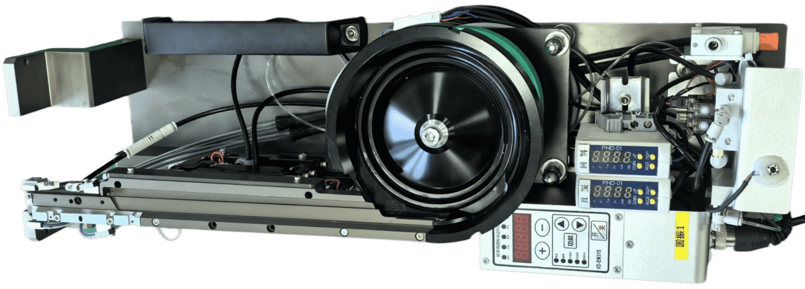
BGA Solder Ball Feeder
Application Scenarios
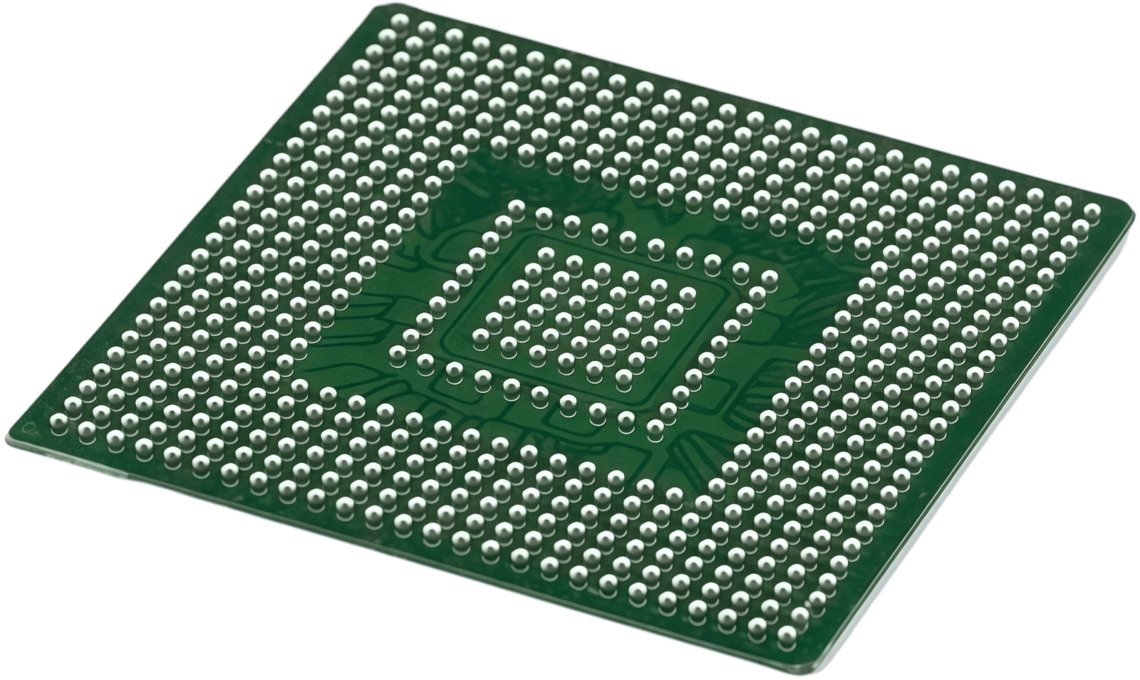
In PCB-side BGA attachment, solder spheres are positioned on a substrate’s pad array before the subsequent assembly stage. In PoP manufacturing, the ball arrangement establishes connections between stacked packages. Other applications include semiconductor rework, module interconnections, grounding structures, and spacer-ball placement where a controlled gap is required. Each application has its own requirements for material properties, pad geometry, placement sequence, and downstream bonding.
Machine Compatibility
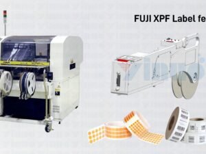
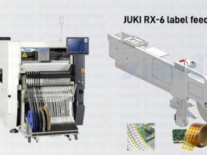
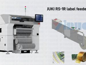
Machine adaptation involves both mechanical and software considerations. The feeder must occupy a suitable mounting position, and the programmed pickup coordinates must correspond to the actual ball presentation point. Supported equipment may include ASMPT SIPLACE, YAMAHA, FUJI, PANASONIC, JUKI, and SAMSUNG platforms, subject to model-specific verification. Before installation approval, the manufacturer should assess mounting dimensions, nozzle access, gantry travel, and the intended production sequence.
Process Notes
SAC305, SAC405 or SAC404, pure tin, and low-melting-point alloys may be considered where appropriate to the application, but alloy selection must follow package and process requirements. Reflow conditions should be validated against the selected alloy’s melting range and the substrate’s thermal limits. For miniature balls, surface oxidation and contamination deserve particular attention. X-ray inspection can help assess hidden joint formation and voiding, while the applicable acceptance threshold should come from the customer’s specification rather than a universal assumed limit.
Information Required for Selection
To identify a suitable configuration, provide the ball diameter, alloy or spacer material, target pitch, substrate dimensions, placement machine model, and expected production volume. A sample of the actual balls can also help establish whether bowl feeding or indexed presentation is the more appropriate approach. Where machine constraints or placement requirements exceed the feeder’s practical capabilities, a dedicated ball attachment system should be evaluated.
Our website is: www.esmte.com | Contact email: info@allaismt.com | Video channel: https://www.youtube.com/@allaismt/videos | WhatsApp: +8613760481664